Week5 & 6: Water Gutter Design and Solar System Connections
This week, I focused on the design of water gutter and finished the BOMs. For the water gutter, the main purpose is to collect the water and reuse it. In Figure1, a water gutter was designed so that it prevents leaves from falling into the gutter, which may cause the flowing of water gutter. This design will then be implemented with my ME106 project ( see Figure 2).


Figure 1: A design for water gutter with helmet
In Figure 2, I will use a turbidity sensor to sense the quality of water and an ultrasonic sensor to measure the water level inside a container. When the detected water is clean, a valve will be opened to let the clean water goes in while the valve for the dirty container remaining close. All the data will then be collected by using Matlab.

Figure 2: A block diagram to show how the clean water will be collected
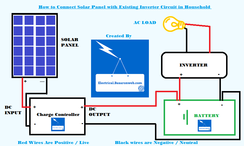
Also, I did some research and helped my partner completed the bill of materials. All the materials that we need for the project includes the extension wires, charger controller, battery, and a transformer. Noticed that in Figure 3, there is an inverter after the battery; however, it will be replaced by a transformer to supply a 12V DC voltage and a 150W output for the control team (see Figure 4). Other parts to build the project will be buying from Renogy company.

Figure3: A simple model for Solar Panel System connection

Figure 4: A transformer will be used to supply the power to a DC motor


Figure 1: A design for water gutter with helmet
In Figure 2, I will use a turbidity sensor to sense the quality of water and an ultrasonic sensor to measure the water level inside a container. When the detected water is clean, a valve will be opened to let the clean water goes in while the valve for the dirty container remaining close. All the data will then be collected by using Matlab.

Figure 2: A block diagram to show how the clean water will be collected
Also, I did some research and helped my partner completed the bill of materials. All the materials that we need for the project includes the extension wires, charger controller, battery, and a transformer. Noticed that in Figure 3, there is an inverter after the battery; however, it will be replaced by a transformer to supply a 12V DC voltage and a 150W output for the control team (see Figure 4). Other parts to build the project will be buying from Renogy company.

Figure3: A simple model for Solar Panel System connection

Figure 4: A transformer will be used to supply the power to a DC motor

Comments
Post a Comment