Posts

Week2: New Design Idea for 6m Long Prototype

Image
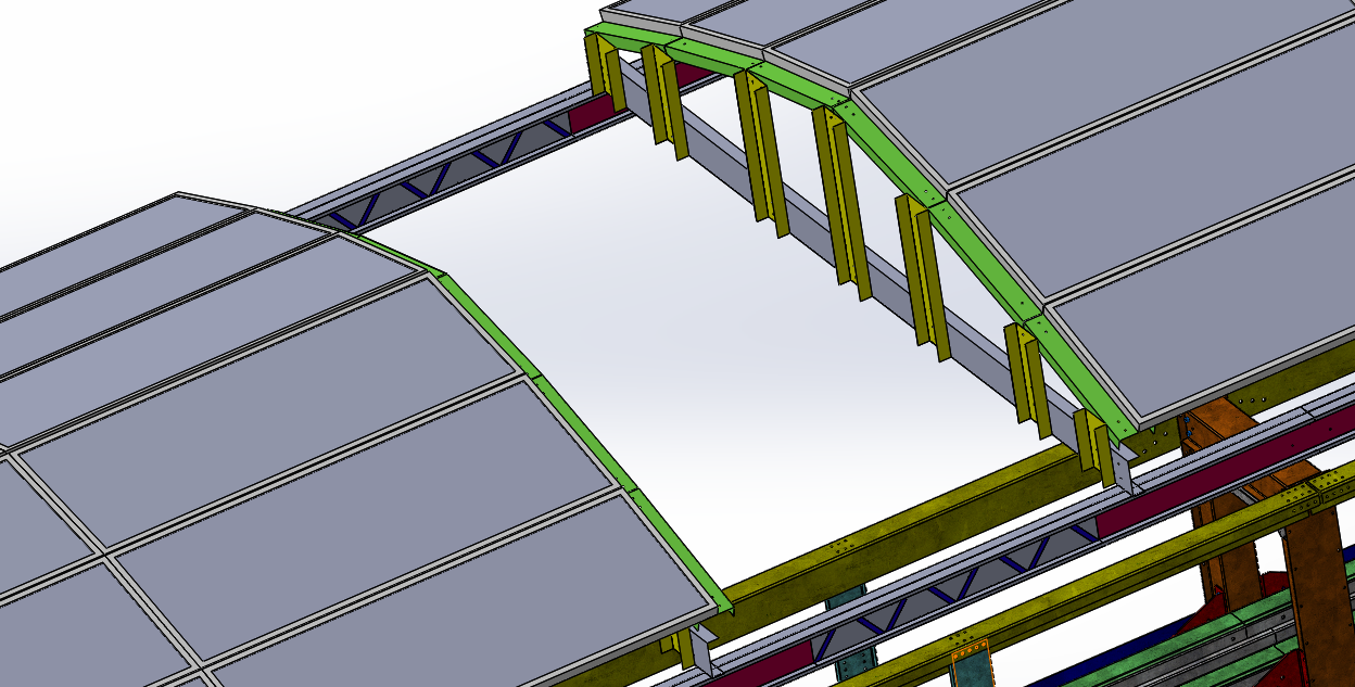
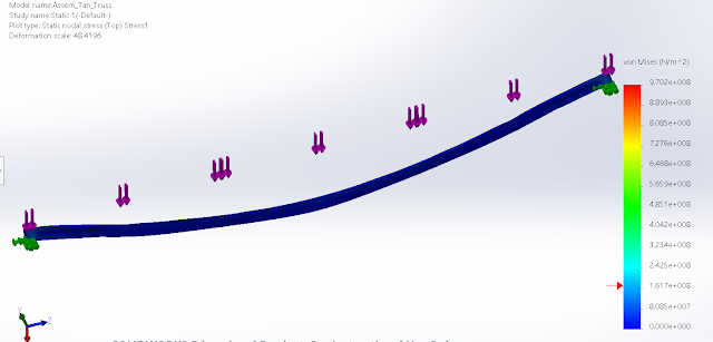
New Design Idea for 6m Long Prototype To achieve a curvature design, we need  to use the flexible steel roof panels. Below picture is one of the options for steel roof panels. The new design has three main layers. The first layer (bottom layer) is the solar rack, it then be covered with steel roof panels. The top layer is the solar panels. Figure 2: Three layers are connected by screws. To connect solar panel with the c channels under the steel roof panels, L brackets have the shape like in Figure 3 can be implemented. Figure3: Two L brackets are connected together by a bolt. This allows the top bracket to be parallel with the solar panel.
Week1: First Meeting for the Spring Semester

This week we had a first meeting. My team and I were working on the bill of material. According to Ron, the full scale prototype now has to be shortered by 6m, instead of 9m long. This is a big challenge for the solar team because we have to change our previous design to meet the new requirements and aslo to reduce the cost of materials.

Week 16: Final Report

For the week 16th, I focused on writing up the final report. My part was working on Chapter 3 of the final report, the Design Solution. While finishing up my team design solution, I noticed that I need to do some research on how to mount the solar panels into the solar racks. For that, I am going to finish the design during the winter break and get it ready to discuss with my team when the Spring semester starts again.  

Week 15 Utilizing Studs for Vertical Support Beams

Image
Over the past few weeks, I was doing some research on how to interconnect the sheet metals to construct more stable and lighter support beams.  Due to the fact that we are limited to two supports, the design of the horizontal beams has to be strong enough to withstand the vertical weight of racking systems and solar panels (see Figure 1). In Figure 2, my team and I was able to come up with a better idea that utilized steal studs.  As a result, by combing the studs together, the new tested design was much stronger and lighter.  Figure1: I-beam was made by combing two opposite side of studs Figure 2: New design was implemented to have a completed assembly  I also used steel studs to design the solar rack. The new design was similar to the previous design; however, the way we connect the parts together would be by using rivet gun (see Figure 3). Figure 3: Utilizing  steel studs for new design can reduce the cost  and the weight of the s...

Week 13 Lockweed Martin Presentation

Image
This week, I focus more on SolidWorks design and simulations and prepare for the Lockheed Martin presentation. In Figure 1, it should that our idea of using sheet metal support beam would not work. Therefore, next week my team and I will focus more on another design. Solomon's knot steel, it's the interconnection of sheet metals, is one of the solutions that we think is possible for the truss design. Figure 1: Simulation shows that the attempted design does not work.  Figure 2: Another solution that can be used for the horizontal supports.

Week 11 & 12

Image
The goal for these two weeks were to get the design ready for the Lockeed Martin presentation on November 15th.  For week 11 and 12, I focus more on designing and improving the existing design from Futran.In their designs, the solar panels are 1.6x1 m; therefore, the total length will be more than 9m if we are going to build at least 9m long track. For week 13, my team and I have to have a solid design with a stress analysis on ANSYS.    Figure 1: Assemble of two supporters and a cross canopy. Figure 1 is an assembling of two supporters and a solar racking system. The new design has two cross trusses that were added to support the weight of the frame and the solar panels. Figure 2: Using truss that was made out of sheet metal Using sheet metal to construct the full-scale designs are considered as a low cost and lighter weight compared to I beams. If it was folded correctly it will generate alot stronger structure, thus it's more efficie...

Week 10: New Design for Solar Racking System

Image
This week, I focused on improving my team's design. If we use the shell design for the canopy it will be more complicated. Therefore, I have have to change my idea to a point where my team and I can manufacture the prototype at the end of the Spring semester.  In Figure 1,  the design for the racking system is much simpler than the shell design that my team had before. However,  it will not be able to support the track as what my team's aim to design for.  Figure 1: Curved Design for Racking System (source http://www.wattlots.com/GroundArbor-Solar-Panels.asp) For the truss design, we may use the studs from Homedepot. Figure 2: Some of the available stubs in the market