Posts

Week 13 and week 14: Fabricating the Prototype and Work on the Finite Element Analysis

Image
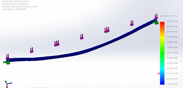
In these two weeks, I focused on building the prototype and finishing up the FEA for the solar rack. For building the prototype, I meet up with my team to fabricate the prototype and to figure out the best way to building the parts faster.  Below is the progress that I make so far on the hand-calculation drag coefficient and drag lift. These data will be implemented in ANSYS to run for the FEA in next couple days. Source: https://file.scirp.org/pdf/JFCMV_2016012909451497.pdf Wind analysis including cooling effects and lift prevention. D d = C d ⍴ V 2 2 A D l = C l ⍴ V 2 2 A Where D d is wind drag   D d , D l : drag and lift forces, C d , C l : drag and lift coefficient relatively, ⍴ is the density of air, V is velocity of wind which has V peak and V storm , and A is the reference area or cross-sectional area of the lowest point of calcul. Wind load calculation has to be calculated using the following values. ⍴ = 1.225 kg/m 3 , V could be...

Week 11 and 12: Working on CFD and Presentation

Image
This week, I still worked on the CFD and prepared for the second presentation. There were updates on meshing methods as well as the other setups, see the result below.  The drag force and lift force got improved comparing to the previous simulation; however, the drag- coefficient and lift- coefficient still do not make sense.  For the next step, I will talk to Dr.Thurlow and other people who have more experience in CFD to take a look at my setup.  After that, I will work on FEA to complete our analysis. 

Week 9 and 10: Manufacturing the Solar Rack and Finalizing the CFD Solutions

Image
In these two weeks, I was working with my team to build the solar rack. I was learning how to use the band saw to cut the C- channel. It was time-consuming; however, I was able to cut the C-channels faster. For the CFD, I was able to improve the meshing and get better with setting up the simulation. In Figure 1, the result of drag and lift coefficient, and drag and lift force were succesful calculated. This result will then be used to calculate for FEA, the stress analysis. Therefore, I will be able to test to see if either my team's design work or not. Figure 1: Results of CFD simulation to find for drag and lift coefficient, and drag and lift force In Figure 2, it shows how the velocity behaves when it hit the wall. In this case, the wall is the curved solar panel rack. When wind hits the top of the curvature wall, it generates a maximum wind speed on the top and a minimum speed at the bottom. This behavior of the wind creates a pressure difference between the top and...

Week 7 and 8: CFD Simulation and Updated Bill of Materials

Image
In the week 7 & 8, I focused on the Bill of Materials and CFD simulation. For the Bill of Materials, I figured out what components to buy such as charge controller, converter, transformer, and batteries. Since the motor from the Bogies team needs a power of 150W and run on DC voltage, it is necessary to have a transformer that can supply an exact power of 150W to the team. The updated Bill of Materials can be seen in Figure 1 below. Figure 1: Bill of Materials for added components For the CFD simulation, I was learning how to use the software and how to set up the boundary conditions to get the most accurate result. In the video, it showed my progress on learning CFD simulation. I expect to finish in week 9, so that I can use the result such as drag coefficient, drag force, drag lift, and lift force from CFD simulation to run the FEA. 

Week5 & 6: Water Gutter Design and Solar System Connections

Image
This week, I focused on the design of water gutter and finished the BOMs. For the water gutter, the main purpose is to collect the water and reuse it. In Figure1, a water gutter was designed so that it prevents leaves from falling into the gutter, which may cause the flowing of water gutter. This design will then be implemented with my ME106 project ( see Figure 2). Figure 1: A design for water gutter with helmet In Figure 2, I will use a turbidity sensor to sense the quality of water and an ultrasonic sensor to measure the water level inside a container. When the detected water is clean, a valve will be opened to let the clean water goes in while the valve for the dirty container remaining close. All the data will then be collected by using Matlab. Figure 2: A block diagram to show how the clean water will be collected  Also, I did some research and helped my partner completed the bill of materials. All the materials that we need for the project includes th...

Week3: Full-scale Meeting

For week3, my team and I had a meeting with Dr.Furman and the management team. We discussed with the clients to see what were the requirements they had so we could change our design to meet their requirements. The two main requirements that the clients asked were the curvature of the solar rack design and the water gutter. Therefore, next step for our team is to change the design.

Week 4: Solar Charge Controller with Solar Panel

This week, I did some research on the solar panel system. To have a fully functional structure for the Maker Faire,  we need a system that can provide enough energy for the full-scale bogie. For that to happen, we need a solar charge controller and a DC to AC inverter. There are various options to buy the solar charge controller and the inverter; however, we need to know for sure the total power output of eight solar panels before we can purchase them. For this week, my solar team needs to talk to Dr. Furman and full-scale team to ensure we are on the right track before we buy the solar charge controller and the inverter.

Week2: New Design Idea for 6m Long Prototype

Image
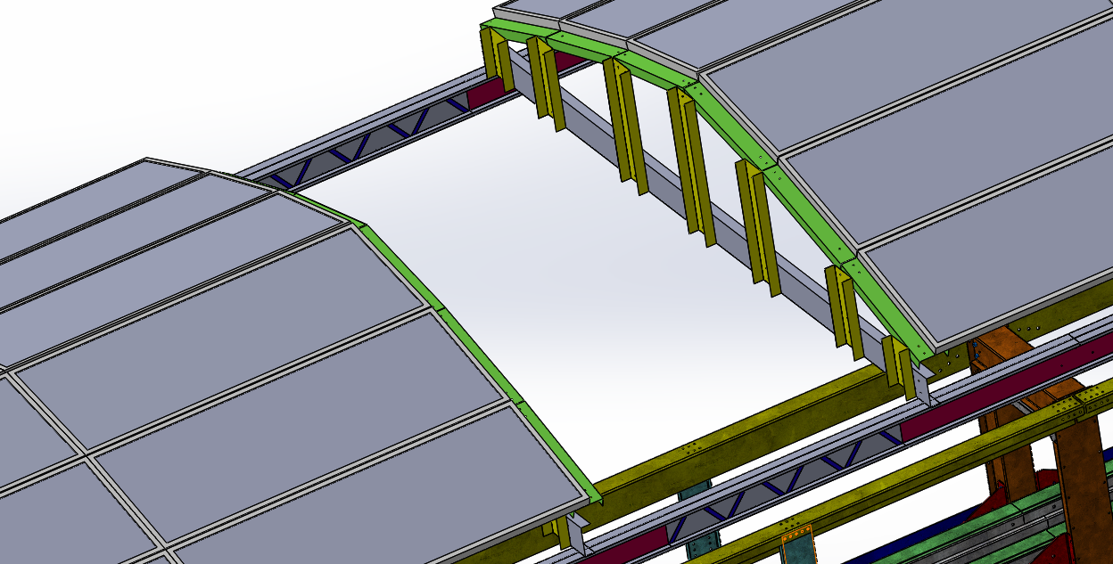
New Design Idea for 6m Long Prototype To achieve a curvature design, we need  to use the flexible steel roof panels. Below picture is one of the options for steel roof panels. The new design has three main layers. The first layer (bottom layer) is the solar rack, it then be covered with steel roof panels. The top layer is the solar panels. Figure 2: Three layers are connected by screws. To connect solar panel with the c channels under the steel roof panels, L brackets have the shape like in Figure 3 can be implemented. Figure3: Two L brackets are connected together by a bolt. This allows the top bracket to be parallel with the solar panel.

Week1: First Meeting for the Spring Semester

This week we had a first meeting. My team and I were working on the bill of material. According to Ron, the full scale prototype now has to be shortered by 6m, instead of 9m long. This is a big challenge for the solar team because we have to change our previous design to meet the new requirements and aslo to reduce the cost of materials.

Week 16: Final Report

For the week 16th, I focused on writing up the final report. My part was working on Chapter 3 of the final report, the Design Solution. While finishing up my team design solution, I noticed that I need to do some research on how to mount the solar panels into the solar racks. For that, I am going to finish the design during the winter break and get it ready to discuss with my team when the Spring semester starts again.  

Week 15 Utilizing Studs for Vertical Support Beams

Image
Over the past few weeks, I was doing some research on how to interconnect the sheet metals to construct more stable and lighter support beams.  Due to the fact that we are limited to two supports, the design of the horizontal beams has to be strong enough to withstand the vertical weight of racking systems and solar panels (see Figure 1). In Figure 2, my team and I was able to come up with a better idea that utilized steal studs.  As a result, by combing the studs together, the new tested design was much stronger and lighter.  Figure1: I-beam was made by combing two opposite side of studs Figure 2: New design was implemented to have a completed assembly  I also used steel studs to design the solar rack. The new design was similar to the previous design; however, the way we connect the parts together would be by using rivet gun (see Figure 3). Figure 3: Utilizing  steel studs for new design can reduce the cost  and the weight of the s...

Week 13 Lockweed Martin Presentation

Image
This week, I focus more on SolidWorks design and simulations and prepare for the Lockheed Martin presentation. In Figure 1, it should that our idea of using sheet metal support beam would not work. Therefore, next week my team and I will focus more on another design. Solomon's knot steel, it's the interconnection of sheet metals, is one of the solutions that we think is possible for the truss design. Figure 1: Simulation shows that the attempted design does not work.  Figure 2: Another solution that can be used for the horizontal supports.

Week 11 & 12

Image
The goal for these two weeks were to get the design ready for the Lockeed Martin presentation on November 15th.  For week 11 and 12, I focus more on designing and improving the existing design from Futran.In their designs, the solar panels are 1.6x1 m; therefore, the total length will be more than 9m if we are going to build at least 9m long track. For week 13, my team and I have to have a solid design with a stress analysis on ANSYS.    Figure 1: Assemble of two supporters and a cross canopy. Figure 1 is an assembling of two supporters and a solar racking system. The new design has two cross trusses that were added to support the weight of the frame and the solar panels. Figure 2: Using truss that was made out of sheet metal Using sheet metal to construct the full-scale designs are considered as a low cost and lighter weight compared to I beams. If it was folded correctly it will generate alot stronger structure, thus it's more efficie...

Week 10: New Design for Solar Racking System

Image
This week, I focused on improving my team's design. If we use the shell design for the canopy it will be more complicated. Therefore, I have have to change my idea to a point where my team and I can manufacture the prototype at the end of the Spring semester.  In Figure 1,  the design for the racking system is much simpler than the shell design that my team had before. However,  it will not be able to support the track as what my team's aim to design for.  Figure 1: Curved Design for Racking System (source http://www.wattlots.com/GroundArbor-Solar-Panels.asp) For the truss design, we may use the studs from Homedepot. Figure 2: Some of the available stubs in the market

Week 9: SolidWorks Design

Image
This week, I started designing on SolidWorks. My team and I was unsure about how the design should look like; therefore, the design that I have was not our final design. This week, I am going to talk with other full scales team to discuss more about the design.  Since my team is going to use sheet metals to design the racking system for solar panel, we have to follow some rules. For example, in Figure 1, the  distance from outside mold line to the bottom of the cutout should be equal to  2.5* Material Thickness + Bend Radius.  When using a punch press tool we should never use a tool who’s diameter is less than that of the material’s thickness etc. Figure 1: Design with sheet metals has to follow some rules Figure 2: Use sheet metals  to connect trusses together Besides, I figured out an easy way to connect sheet metal truss together by using bent sheet metal pieces.

Week 8: Power Calculation & Sketch Designs

Image
Design I: Top part of the racking system can be used for delivering. Design II: This design allows the designer to change the shell shape of solar panels to meet aesthetic requirements. Design III: Using cable to hole the canary. Some change for power calculation : M = 400 #(kg) Mass of fully loaded ATN vehicle M_v = 400 # vehicle + bogie mass, kg V_l = 1.5 # line speed, m/s V_w = 1.5 # average wind speed, m/s D_s = 9 # distance between stations, m A_v = 1.5# frontal area of a vehicle, m^2

Week7: Energy Calculation from Dr.Furman's Code

This week I did  some  research on solar panel racking system designs. Also, I used the code from Dr. Furman to calculate the power that is needed to run 1 pod car. Since we will build a 9 m long full scale  prototype, some values are needed to be changed. Assumptions : M = 100 #(kg) Mass of fully loaded ATN vehicle M_v = 1900 # vehicle + bogie mass, kg V_l = 1.5 # line speed, m/s V_w = 1.5 # average wind speed, m/s D_s = 9 # distance between stations, m Results: ** Energy per vehicle ** Energy required, E(t_s) = 1.08e+05 J Average trip time, 0.5 minutes Average power, P_avg = 3,927 W >> Energy per 150 vehicles << Energy required, E(t_s) = 1.626e+07 J Average trip time, 0.5 minutes Average power, P_avg = 5.89e+05 W KE loss = 9.26e+01 J ---> 0.1% Air drag loss = 2.94e+01 J ---> 0.0% Rolling resistance loss = 1.19e+02 J ---> 0.1% Elevation loss = 1.15e+04 J ---> 10.6% Aux power loss 9.66e+04 J ---> 89.1%

Week 6: Energy Calculation

This Week,  Considering to last week presentation's comment from Dr. Furman, I spend time try to understand the  power calculation that Dr. Furman gave me. Therefore, I know how many panels are going be used for the 9m full scale prototype, as well as the cost and the size of each panel.  Next week, my team and I will start designing the racking system for solar panels. 

Week5: Options for Solar Panel

Image
Week5:                                      Pros and Cons of Three Main Solar Panels Currently, we have three main solar panels that are widely used throughout the world. There are monocrystalline silicon solar panels, polycrystalline silicon solar panels, and thin-film solar cells (Eric Rosenfeld). 1) Monocrystalline Silicon Solar: (pros) efficiency of 15-20%, it has the highest efficiency of the different types of solar panels, a long life span, and produces the most efficient result under low light conditions. (cons) it is the most expensive among the three types of solar panel 2)Polycrystalline: (pros) cost less compared to monocrystalline silicon solar panels. efficiency of 13-16% (cons) They require more space in order to produce the same amount of power output compared to monocrystalline. 3)Thin film: (pros) they are aesthetically appealing due to the ability to...

Solar Panel Racking Design

Image
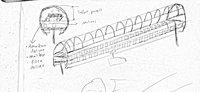
Week 4:                                     Solar Panel Racking Design For this week, I continued reading the existing research  and  related projects to have a better picture of the solar panel racking design and to find a solution for solar panel position. In term of racking design for solar panel, since we have to build a 18m long track that only have two supported poles at each end of the track, my team and I thought that it would be better to change the direction of the roof rack so that the weight of the roof would act upon the two supported poles rather than along the tracking itself. To have a better visualization, the following sketch can explain it all. In addition, the new design could help support an upward force on the track. Therefore, the track would be more stable.  For solar panel position, the best solution is to have a curved design with an tilted angle of...